
Create a Face Map
To access this screen:
-
Activate the Map ribbon and select New.
-
Using the Project Data control bar, expand the Map Directory folder. Right-click the Maps folder and select Add Map.
Add a new map to the current database. A face map is comprised of one or more faces oriented around a cube of specified dimensions.
A face map is supported by both map and 3D world windows. The resulting map is georeferenced using either one or two points.
The Add Map screen fills out the Map name automatically if your System Configuration File contains a naming convention, otherwise, it is blank and a name must be entered.
Notes:
- When a map is created, it is added to an internal database of map names and creation dates/times.
- Data files associated with a map will also include alphanumeric data columns describing the MINE, AREA and MAPNAME associated with the map to which the data belongs. This applies to all data files.
- Each time a map is created, a time stamp is added to the corresponding file. It is this date that is used to determine if map data is included in an export.
- If an attempt is made to create a duplicate map name (map names are not case-sensitive) an automatically-incremented index will be added to the end of the map name, in brackets, e.g. MAP20201310(2), MAP20201310(3) and so on.
Map Types are listed based on the contents of your configuration file. Each type determines the type and number of faces included in your map.
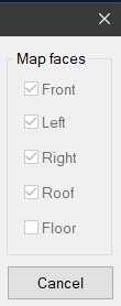
If no types are defined in the external file (or no configuration file is specified), the list will show "<none>" and you will be able to select one or more faces to include using the Map faces options.
These are unchecked if a template map type has been selected (as defined by your configuration file), but will check the faces the preconfigured selection represents, unless the map is of the
System Administrator's Note: the projection type must be specified in your system configuration file using the <UseAutomaticOverlayMode> tag. This setting determines if 2D or 3D plot projections are used in output PDF reports, and applies to all reports created for all maps of the same map type.
For example, a <Maptype> "Heading" is defined in the configuration file, and selected. The face represents a drive face and two sidewalls. The Map faces check boxes are inactive, but display checked faces representing the selection:
Note: change the existing map to be a different map type using Home ribbon >> Current Map >> Change Type. See Change Map Type.
For each face, define the Width, Height and (if multiple faces exist) the Depth of the cuboid around which faces will be added. If a single face is selected, Depth is ignored.
Tip: If you are using a portable device, automatically display a screen keyboard for easier data entry at the face. Enable screen keyboard mode using the Setup ribbon's On-Screen Keyboard command.
Butterfly Maps
Face maps can be unfolded to show all faces in the same plane. This is known as a 'butterfly map'.
-
3D Face Map views show each face as a side of a cube. Each face aligns with a particular section representing up to 5 faces (front, top/backs, left wall, right wall and floor). Changing map faces automatically orients the cube so you are viewing the target face orthogonally, for example:
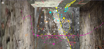
(Perspective mode is enabled in the above view. See Navigation Toolbar)
-
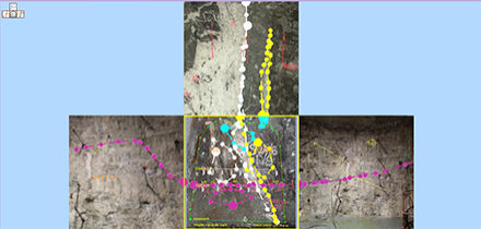
Butterfly map views align all faces to the same plane so they can all be viewed orthogonally at once. This can be advantageous when digitizing polygon or contact features across faces. The data shown in a butterfly map view hasn't been flattened; it simply appears that way to make it easier to create face content. For example:
Swap between 3D map and butterfly map views instantly using the on-screen icon at the top left of the viewing area:
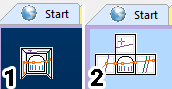
(1) shows the icon in 3D map mode, whilst (2) denotes the view is currently in butterfly map mode. Clicking the icon toggles between the two states.
Note: Swapping between map views doesn't affect any underlying data; only the view of the data changes. View icons do not appear in the 3D world view.
To create a New Map:
- With the New Map screen displayed, either accept the default name (or edit it) or create a new name. This field is always editable.
- Select a Map type, or select [<none>] to define your own face selection using the Map faces options. At least one face must be selected.
- Define the Width and
Height and (optionally)
the Depth of the face
map cuboid. The dimensions you set will appear as initial values
for the next map. These values are stored in the project so will also
be available in future project sessions.
-
Click OK to create a new map and dismiss the New Map screen.
The new (and associated data) is added to the current database when the project is next saved (until then, no physical files are created).
Notes:
- Map names cannot contain special characters (back slash, forward slash etc.)
- Map dimensions can be edited after a map has been created, using the Map Properties panel.
Related topics and activities